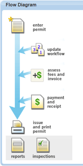
Creating User Flow Diagrams
You use the My Navigation portlet to define user flow diagrams. Flow diagrams provide users with a visual representation of the steps they follow to accomplish specific tasks. The icons in the flow diagram link to the portlets or URLs from where users perform their tasks.
To create user flow diagrams
Access the My Navigation portlet (Accessing the My Navigation Portlet>).
Delete an existing flow diagram.
Locate an existing flow diagram by clicking on it in the My Navigation Name column or by searching for it.
Click Delete.
Edit an existing flow diagram.
Locate an existing flow diagram by clicking on it in the My Navigation Name column or by searching for it.
Complete the flow diagram configuration ().
Create a new flow diagram.
Click New.
Complete the flow diagram configuration ().
Complete the flow diagram configuration.
Complete the Diagram General tab.
My Navigation Name Enter the name for the new flow diagram. For example, you might enter “Counter Clerk” for a diagram to assist counter clerks with a simple workflow process for issuing a permit. Description Enter a description of the flow diagram. For example, you might enter “Counter Clerk workflow for issuing a new permit.” Comments Enter any comments about the flow diagram. The entered comments display at the bottom of the flow diagram portlet. Complete the Flow Nodes tab.
Delete a flow node.
Select the checkbox next to the flow node(s) you want to delete.
Click Delete.
Change the order of the flow nodes.
Modify the order number(s) next to the flow node(s) you want to reorder.
Click Submit.
Add a new node.
Click the New Node button.
Select the link type (portlet or URL) for the new node.
Click Submit.
Edit an existing node.
Click the hypertext link for the node you want to edit.
Define new node parameters or edit existing node parameters (Table 1).
Table 1. Flow Nodes Fields Order Indicates the relative order of the flow node (lowest/top to highest/bottom) in the overall diagram. Two nodes with the same order number appear on the same line in the flow diagram. Portlet For portlet link type only. The name of the portlet for the flow node. Icon For URL link type only. Select the icon you want to use for the flow node from the Icon drop-down list. Target The portlet frame the flow node points to.capForm. Specifies the form portlet frame.capList. Specifies the list portlet frame. Text Align The alignments of the text that displays next to the flow node icon. Text The text you want to display for the flow node icon. Alternative Text The text you want to display as the alternate text for the icon. The alternate text displays when the cursor hovers over the icon. URL For URL link type. The URL to the portlet for the flow node. Onclick Specifies the JavaScript function to run when a user clicks the flow node.doReport(). Runs a report.new(). Creates a new record. Complete the Recipient tab (Setting Up Security Policies).
Click Submit.